How to Install a Manual Transfer Switch for a Portable Generator
Steps:
Mount the manual transfer switch near the main electric panel.
Select up to 10 circuits to be powered by the generator (240 volt circuits require two spots on the transfer switch).
Turn off power to the house at the main electric shut off.
Remove the cover on the main electric panel (work inside the electric panel is only recommended for licensed electricians).
Locate an available knockout hole on the electric panel and remove the plug. Attach the armored cable from the transfer switch to the electric panel.
Connect the ground and neutral wires from the transfer switch to the appropriate bus bars on the main panel.
Locate the first circuit to be powered by the generator and remove the power wire on the existing circuit breaker. Replace that wire with the red wire from the transfer switch marked “A.” Splice the black wire marked “A” from the transfer switch to the removed power wire using a wire nut. Repeat this process for all 10 circuits, ensuring the red and black wires from the transfer switch are a matched pair.
Use 10-3 non-metallic wiring to connect the transfer switch to a power inlet outside.
Use the provided generator cord to connect the power inlet to the generator (or make your own cable if a longer one is desired using bulk wire and connectors).
Ensure the generator has unleaded fuel and oil inside, then start the generator.
To test the wiring connections, flip the switches on the transfer switch from “Line” to “Gen.” The generator should power the selected circuits.
Best Practices for Replacing Antique Light Switches
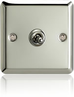
I’d recommend that you replace the original switches with new ones. Those switches were made with materials that may have become cracked, corroded, or fatigued in the last 100 years, and their design doesn’t meet today’s strict electrical-safety standards.
Fortunately, you don’t have to give up on the two-button look, or the satisfying snap that the buttons make when you push them in. Replacement switches and cover plates that look just like the antique versions, right down to the mother-of-pearl inlay on the buttons, are available from specialty retailers such as House of Antique Hardware.
Cost
Prices for a basic, single-pole, push-button switch begin around $14. You can also get an authentic-looking push-button dimmer switch, with one rotating button that functions as the dimmer.
Safety
The more important question to ask about a house of this age is: How safe is the wiring? I’ve seen electrical systems that have provided 100 years of service, or more, and l know what a high fire and electrical-shock hazard they pose. You’d be wise to take a close look and see what you’ve got.
SWITCHING GUIDE | DJT ELECTRICAL TRAINING
IMPORTANT: CORONAVIRUS
We are delighted to announce that DJT reopened for business from May,
with exceptional provisions in place to cater for the COVID19 requirements.
These provisions include:
Every surface has been deep-cleaned &/or repainted in full since the lockdown was implemented & is re-cleaned daily during courses
We have halved group sizes from a maximum of 24 to a maximum of 12 delegates at any one time to allow correct distances between the chairs & desks
We have developed a pre-course questionnaire which must be completed 48 hours prior to a course by anyone attending training
We will now run courses for groups as small as 6 delegates (whereas 10 used to be the minimum number)
We have purchased the FLIR E5 thermal-imaging camera for facial-temperature imaging, which we administer in seconds before training commences (pic attached)
We have non-contact LPOW HTD thermometer to take daily forehead-temperatures in seconds & record & display the results to the delegates
We have lowered the number of delegates taking their exams at any one sitting, in order for all delegates being examined to ensure the correct distancing between terminals
In electrical installations a switch is an electrical component that can break an electrical circuit, interrupting the current or diverting it from one conductor to another. The most familiar form of switch is a manually operated electromechanical device with one or more sets of electrical contacts. Each set of contacts can be in one of two states: either ‘closed’ meaning the contacts are touching and electricity can flow between them, or ‘open’, meaning the contacts are separated.
A switch may be directly manipulated by a human as a control signal to a system, such as to control power flow in a circuit, as in a light switch, or to isolate a supply, such as a Firemans switch. Automatically-operated switches can be used to control the motions of machines, for example, to indicate that a garage door has reached its full open position or that a machine tool is in a position to accept another work piece. Switches may be operated by process variables such as pressure, temperature, flow, current, voltage, and force, acting as sensors in a process and used to automatically control a system. For example, a thermostat is a temperature-operated switch used to control a heating process.
N/O & N/C Switches
In a push-button type switch, in which the contacts remain in one state unless actuated, the contacts can either be normally open (abbreviated “n.o.” or “no”) until closed by operation of the switch, or normally closed (“n.c. or “nc”) and opened by the switch action. A switch with both types of contact is called a changeover switch. These may be “make-before-break” which momentarily connect both circuits, or may be “break-before-make” which interrupts one circuit before closing the other.
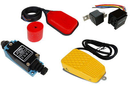
Tilt Switch (SPST)
Tilt switches contain a conductive liquid and when tilted this bridges the contacts inside, closing the switch. They can be used as a sensor to detect the position of an object. Some tilt switches contain mercury which is poisonous.
Reed Switch (usually SPST)
The contacts of a reed switch are closed by bringing a small magnet near the switch. They are used in security circuits, for example to check that doors are closed. Standard reed switches are SPST (simple on-off) but SPDT (changeover) versions are also available.
Electrical Switch Overview
An electrical switch is a binary device, which means that a switch is either on (closed contacts) or off (open contacts). A switch can be any device that opens or closes an electrical circuit, and switches can range in from a simple on-off toggle switch to the large contactors, used to switch high power loads like electric motors, to more complex solid-state switches like a NPN or PNP bipolar transistor switch.
Though there are numerous switch designs, all provide the same basic function of opening and closing a circuit with a set of contacts. The following sections describe the basic components of mechanical switches, introduce important switch terms (e.g. normally-open and normally-closed contacts), and go over types of switches. The last section gives general information on how to select switches.
Basic Components in Electrical Switches
Actuator
A force must act on a switch in order to open or close the circuit, and the device that applies this operating force is called the actuator. Do not think actuating a switch means you are turning something on. Actuation just means changing the state of a switch’s contacts from either open to closed (making a connection) or closed to open (breaking a connection). Thus, a switch can be actuated to turn a device ON or OFF.
Armature
In mechanical switches the moving part of a switch that conducts the current between contacts is called the armature. Levers are commonly used as armatures.
Electrical Contacts
Wherever you have two pieces of conductive material separated by an insulated gap and connected to a circuit, you have electrical contacts. To be of any industrial value electrical contacts must be composed of metals that have a high resistance to corrosion and mechanical wear. There are only two possible states for any set of contacts:
Open / Break / Off – Contacts CANNOT conduct electricity (i.e. there is an insulated gap separating the contacts and preventing current flow)
Closed / Make / On — Contacts CAN conduct electricity (i.e. contacts are connected by some conductive material)
Accessories
Some switches come with attached cables, strain relief, and connectors, while other switches are sold where you just get the switch by itself. Browse our product guides for general information about the selection, function, and use of wires and cable, strain relief for flexible cables, and electrical connectors.
Rewired And Similar Installations
This section incorporates questions relating to:
New or rewired domestic and similar installations
Alterations and additions in domestic and similar premises
New installations (places of work)
You may notice that some numbers are missing from the Q&A. This is deliberate. The regulations are constantly updated and as questions become out of date, we remove them but do not renumber, as we are aware that visitors to the site will note specific numbers for future reference.
Q1.1. Do the Wiring Regulations require all 13 A socket-outlets to be RCD protected?
For new installations and rewires, all socket-outlets with a rated current not exceeding 32A need to have additional protection by RCD, except where other than for an installation in a dwelling, a documented risk assessment determines that the RCD protection is not necessary. It is the view of the forum that any decision to omit RCD protection should not be taken lightly
Q1.2. BS 7671 requires most if not all circuits in domestic premises to be RCD-protected. There have been a number of suggestions as to how the consumer unit may best be configured to comply with the Regulations, the most common being a main switch with RCBOs protecting each individual circuit. However, another suggestion favours a main switch with two RCDs protecting separate DIN rails. If careful consideration is given as to what each bar will control in the way of upstairs and downstairs lighting and power circuits, will this configuration comply?
Yes, as long as the division of final circuits between the RCDs is carefully considered so as to minimize the consequences of unwanted tripping. Separate RCD protection is not necessarily required for each circuit of an installation but, in order to minimize the likelihood and consequences of tripping, a single (‘front end’) RCD should not be used to protect all the circuits.
Q1.3. What electrical equipment and accessories can be installed in the area beyond zone 2 of a location containing a bath or shower basin?
Socket-outlets other than a SELV socket-outlet or a shaver supply unit are not permitted within 3 m horizontally from the boundary of zone 1. In all other cases, only the general rules apply, in that equipment shall be of a design appropriate to the situation in which it is to be used or its mode of installation shall take account of the conditions likely to be encountered.
Q1.4. Do ‘meter tails’ concealed in walls or partitions need to be protected in accordance with Regulations 522.6.202, 522.6.203 and/or 522.6.204?
Yes. Meter tails concealed in a wall or partition at a depth of less than 50 mm from a surface must be protected in accordance with Regulation 522.6.202. Also, irrespective of the depth from a surface, meter tails concealed in a wall or partition having internal metallic parts (except nails and screws, etc.) are subject to the requirements of Regulation 522.6.203.
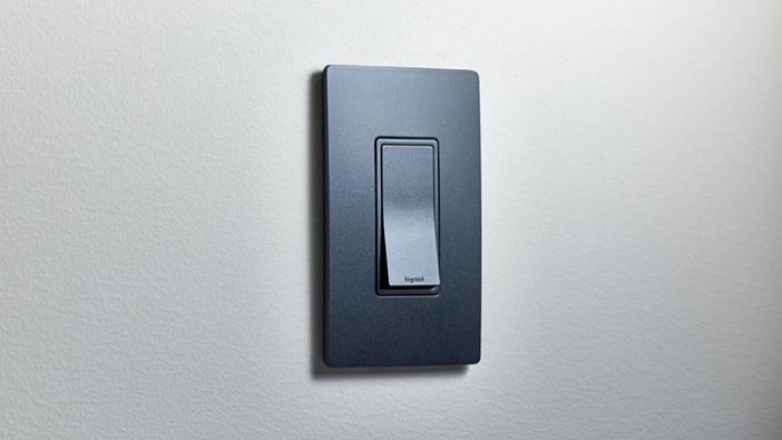
Outlets and Switches Guide
Outlets and switches can be easily overlooked in your home, but these functional pieces of hardware let you light, ventilate and power your appliances. Technological advances are giving outlets and switches exciting new capabilities, so learn what they can offer before you buy.
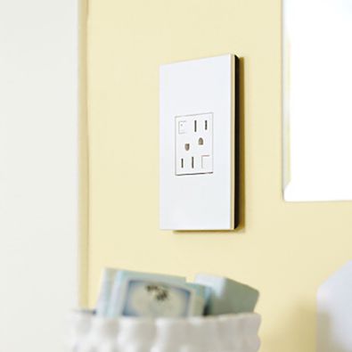
Outlet Types
Outlets make power easily accessible. They can also prevent electrical fires, keep users from being shocked and be turned on and off remotely. Different outlets have different uses, so learn more before making your purchase.
Amperage: The ampere, or amp, is the base unit of electric current. Outlets are rated by how many amps can flow through them at once without overheating and are attached to fuses that will shut off automatically if your outlet is using too many amps. Most outlets in your home are rated for 15 amps and attached to a 15-amp fuse with a few other 15-amp outlets and switches from the same room. If the total amount of amps used in that room surpasses 15 amps, the fuse will shut off to keep the outlets and wiring from overheating. Some appliances, like freezers and gas dryers, require 20-amp outlets.
GFCI vs. AFCI Outlets: Ground fault circuit interrupter (GFCI) outlets have sensors that measure the amount of current going in and out of the socket. The current going in and out is usually in balance but if the outlet detects an imbalance, it immediately shuts off. GFCI outlets are important to have in areas where electricity could meet, like bathrooms, laundry rooms and kitchens. Arc fault circuit interrupter (AFCI) outlets contain electronic components to monitor a circuit for the presence of dangerous conditions that could cause a fire. This outlet can be triggered to turn a circuit off quickly if dangerous arcing is detected.
Smart Outlets: Smart outlets can be controlled from your mobile device using the home’s wireless internet. These devices allow users to program outlets to power on and off at certain times, as well as control from inside and away from the outlet.
Tamper-/Weather-Resistant: Tamper-resistant outlets have spring-loaded shutters that close off the contact openings where you insert plugs. In order for the shutters to open, both springs must be compressed at the same time, so they don’t open if a child attempts to insert an object into one of the contact openings. Thousands of children suffer shock and burns yearly by sticking items into contact openings in outlets. Weather-resistant outlets offer protection from precipitation, humidity and UV-protected components.